|
@704E.ADF VCA/A adapter (NTSC composite)
@70CE.ADF VCA/A PAL
vcpa.exe High Level Video
Capture Card/A Application Programming Interface
OS/2 1.3, Win3.0, and DOS. 8514A, MCGA, VGA8 video adapters
videocap.com Video Capture Adapter/A Option v1.10
videocap.txt Readme for videocap.com
VCA_Option Video Capture
Adapter/A Option v1.10 in *.rar format
189-101
ACPA, ACPA/A, and Video Capture /A For the IBM PS/2 [VCA 34F2785]
191-192 Enhancements To Audio
/ Video Multimedia Adapters From IBM [VCA 92F3380]
Multimedia
presentation development using the Audio Visual Connection
Video
Capture Adapter base Card
Video Capture Daughter Card
U31 Acoustic delay line
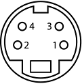
S-Connector Cable Pinout
Primary I/O Cable Pinout (NTSC)
Primary I/O Cable Pinout (PAL) Warning! My best guess!
ADF Sections
Video Capture Adapter Base Card
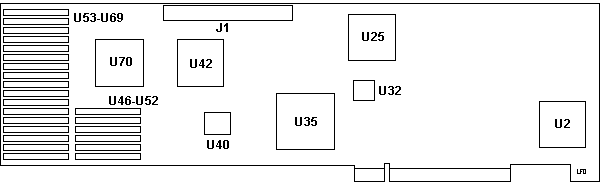
J1 72 Pin Socket
U2 Xilinx XC2064-70 PC68C
U25 Xilinx XC3020-50 PC68C
U32 N82S181CA
U35 Xilinx XC2018-70 PC84C
|
U40 TI -2FML TMS27PC256
U42,70 Xilinx XC2018-70 PC68C
U46-52 TI TMS4461-12SDL (x6) TARAM
U53-69 TI TMS4461-12SDL (x17)
|
TARAM - Translation Address RAM
N82S181CA
Fuse-Programmable PROM - On-Chip Address Decode
Video Capture Daughter Card
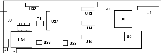
J1 Pads for 26 Pin Header
J2 72 Pin Header
J3 20 Pin Port
J4 S-VHS Port
U5 Brooktree BT101KPJ
U6 Xilinx XC2018-70 PC84C
U13-U15 CA3306E or MP7682KN
|
U22 Motorola MC1377FN
U27 Motorola TDA3330
U29 VTC (?) VA2706DJ
U31 Philips DL-750 361579-6
U32 Philips TDA2595
Y1 3.5795 MHz Crystal
|
CA3306E 6-Bit,
15 MSPS, Flash A/D Converter
MP7682KN CMOS, 6-Bit
High-Speed A/D Converter
TDA2595 Horizontal combination
TDA3330 Philips
TV Color Processor
VA2706DJ Virtual
Training Co: Dual General Purpose Op Amp - SR 42V/us, Io
+/-50mA
MC1377FN Video
Decoder-Encoder Circuit - RGB/NTS encoder
Bt101KPJ Brooktree
Triple 8-Bit Digital-to-Analog Converter
Not shown (yet)
VA706POJ Hi-Speed, Fast
Setting, Precision Op Amp
MX7533JCWE CMOS Low
Cost 10 Bit Multiplying D/A Converter
ICT 93C46P 1,024 Bit
Serial 5V CMOS EEPROM - Holds calibration data.
TTLSWGM-20 TTL
Compatible Square Wave Generator, 20MHz
J1 could be an unimplemented VMC header that was used on
the VCA (ISA bus) version. The MCA version can pull base
video over the AVE connector, and would not need J1.
U31 Acoustic delay line
Philips DL-750 361579-6
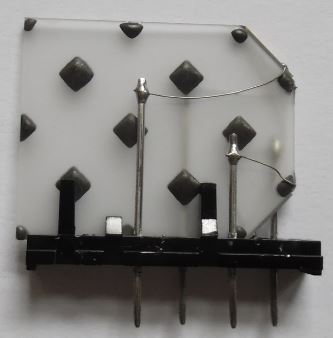
Tomáš Slavotínek:
That thing is a delay line. Acoustic delay line to
be more precise - commonly used in analog television (PAL) to
"store" the last scan line. It's made of glass and each of
the two cut corners has a piezo transducer on its edge.
One transducer is used to generate an acoustic wave, and
the other one is there to detect it. The wave bounces of
the edges and is being directed by the special pattern
created on the glass surface. It has to go all the way
through the "maze" to reach the other transducer. It will
get there but with a certain time delay, and that's what
we are after. Length of the delay depends on the physical
construction. It can act as a primitive memory with the appropriate
support circuitry...
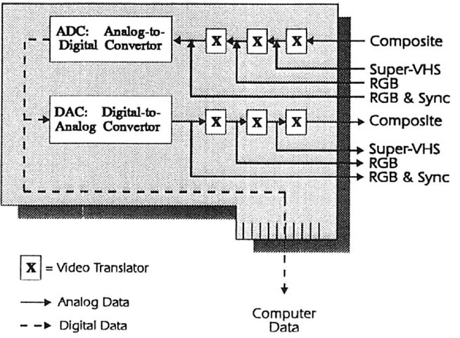
Video Capture Adapter/A
Functional Diagram
Concurrent Engineering Techniques and Applications:
Advances in Theory and Applications, page 303 ISBN:
1-12-012762-8
Video Capture Adapter/A
- Enables user to capture high quality,
photo-like images
- Full frame capture from motion video in 1/30
seconds
- Images can be manipulated and used in high
quality presentations created with AVC
- Uses RGB, NTSC (Composite Video) and Y/C
(Super VHS)
- Captures 65,536 colors with a resolution of
640 X 480 X 16 bits
- Allows viewing live video during capture;
the card is not required for general image presentation
purposes
- 614Kb dual-ported video RAM buffer
- Image display modes live, memory, overlay,
transparent, pixel
The Video Capture Adapter/A can capture,
display and digitize high quality video images. It
supports Models 50, 55 SX, 60, 70 and 80 and is intended
for use with the AVC program.
Ed. Also supported by
Storyboard, Video IN, and Ultimedia Builder/2, among
others.
The adapter accepts video input signals through a multi-pin
connection on the adapter. The on-board processor
converts the analog signal to a digital format that can
be manipulated, compressed and stored by software for
later use. Sophisticated detailed image processing
techniques employed in the AVC Image Editor Components
enable the user to alter the characteristics of the
digitized image as outlined in Programming Announcement
289-333. The video adapter also contains output
connectors, for attachment to a monitor, which allow the
user to view live or captured images during the
capturing process. The adapter display capability
is not required to run presentations containing captured
images. The standard PS/2 hardware alone enables
the complete display of images for authoring and
presentation purposes.
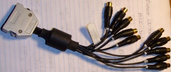
The video adapter end-bracket contains a 20-pin
connector. The cable supports in/out jacks to RGB, NTSC
(Composite Video) and Y/C (Luminance/Chrominance)
devices. Y/C allows significantly higher quality
image than NTSC.
2. The NTSC Primary I/O Cable has ten separate cables
with RCA sockets on a 20-pin connector at the other end.
The VCA/A PAL adapter has a Primary I/O cable with
twelve separate cables which end in RCA sockets, with a
37-pin connector on the other end.
Enclosure on DB20 pin end of cable is JAE
D05-20H-S. JAE Connectors (Japan
Aviation Electronics Industry) D-sub connector shell
20P Crimp pins for 24-30 AWG, D05-20-26P
Ferrite choke over all individual cables, 1" OD, 1/2"
ID, 1" long, 1" from top of enclosure.
3. An S-Video Output Cable is
also used by the diagnostic program for a Y/C Wrap
Cable. This cable has an S-Connector at one end and two
RCA plugs at the other end. The GREEN RCA plug (8) is
the LUMA (Y) cable and the RED plug (9) is the CHROMA
(C) cable.
S-Connector
Cable Pinout
|
| Pin |
Color |
Task |
| 1 |
Red |
Y Gnd |
| 2 |
Green |
C Gnd |
| 3 |
Red |
Y Signal |
| 4 |
Green |
C Signal |
|
This cable is not included with the VCA/A PAL adapter
because it has two extra cables on the Primary I/O cable
which serve as LUMA and CHROMA output connections.
4. Three 75 Ohm male RCA
Terminators.
5. A short cable with male RCA
plugs at both ends which is used by diags in Wrap Tests
for RGB and Composite Video. (VCA/A PAL adapter uses two
of these M-M RCA cables.)
6. Diskette with diags,
related modules, @704E.ADF VCA/A (NTSC) and @70CE.ADF
VCA/A (PAL).
Primary I/O Cable
Pinout (NTSC)
NTSC composite - Leads 1-10 34F2796,
page 3-5.
| Short Leads 1-5 |
| Composite Sync Out |
1 |
11 |
Shield for Comp. Sync Out |
| Analog Blue Out |
2 |
12 |
Shield for Analog Blue Out |
| Analog Green Out |
3 |
13 |
Shield for Analog Green Out |
| Analog Red Out |
4 |
14 |
Shield for Analog Red Out |
| NTSC Output |
5 |
15 |
Shield for NTSC Output |
| Long Leads 6-10 |
| Composite Sync In |
6 |
16 |
Shield for Comp. Sync In |
| Analog Blue In |
7 |
17 |
Shield for Analog Blue In |
| Analog Green or Luma In |
8 |
18 |
Shield for An. Gr. or Luma In |
| Analog Red or Chroma In |
9 |
19 |
Shield for An. Red or Chr. In |
| NTSC In |
10 |
20 |
Shield for NTSC In |
If your RGB monitor lacks 75 ohm term, place RCA
Terms on 2, 3, and 4. If RGB outputs aren't terminated,
Y/C and Comp Video outputs will distort image brightness.
Primary
I/O Cable Pinout (PAL)
Note: 34F2796 is the
NTSC Install/Tech Ref, it has nothing on the PAL pinout.
Note: The PAL version
uses a 37 pin connector? Gurgle... This pinout is VERY
wrong!
| Short Leads OS - IS |
| Comp Sync Out (OS) |
1 |
11 |
Shield for Comp. Sync Out |
| Analog Blue Out (OB) |
2 |
12 |
Shield for Analog Blue Out |
| Analog Green Out (OG) |
3 |
13 |
Shield for Analog Green Out |
| Analog Red Out (OR) |
4 |
14 |
Shield for Analog Red Out |
| Comp Video Out (OV) |
5 |
15 |
Shield for Comp. Video Out |
| Comp Sync In (IS) |
6 |
16 |
Shield for Comp Sync In |
| Long Leads IB - OY |
| Analog Blue In (IB) |
7 |
17 |
Shield for Analog
Blue In |
| Analog Green / Luma In (IG) |
8 |
18 |
Shield for An. Gr. or Luma In |
| Analog Red / Chroma In (IR) |
9 |
19 |
Shield for An. Red or Chr. In |
| Comp Video In (IV) |
10 |
20 |
Shield for Comp Video In |
| Chroma Y/C Out (OC) |
11 |
21 |
Shield for Chroma Y/C Out |
| Luma Y/C Out (OY) |
12 |
22 |
Shield for Luma Y/C Out |
If your RGB monitor lacks 75 ohm term, place
RCA Term plugs on OR, OG, and OB. If RGB outputs are not
terminated, Y/C and Comp Video outputs will distort image
brightness
34F2788 Video Capture Adapter/A (MICROCHANNEL)
34F2789 Video Input/Output Cable
34F2790 Video Y/C Cable (S-CONNECTOR)
34F2791 Video Wrap Cable
34F2792 Video Terminators (Three 75 Ohm RCA Plugs)
34F2794 Video Diagnostic Diskette
AdapterId
0704Eh "Video Capture Adapter/A"
Video Storage Address Select
System memory addresses. D400-DBFF or D800-DFFF is
recommended. At least 2 16k blocks are recommended for
card memory to card memory operations. If another
choice must be made, try to use a selection with the most
pages. The protect mode selection may be used if your
operating system supports 'protect mode' such as OS/2. DOS
does not support 'protect mode'."
<"C0000-C3FFF">,
D000-DFFF, D400-DBFF, D800-DFFF, D000-D3FF
/ D800-DBFF, D000-D3FF /
DC00-DFFF, D400-D7FF / DC00-DFFF, D000-D3FF / CC00-CFFF,
D000-D3FF / C000-C3FF, D400-D7FF / C000-C3FF, D400-D7FF
/ CC00-CFFF, D800-DBFF / C000-C3FF, D800-DBFF /
CC00-CFFF, CC00-CFFF, D800-DBFF, F6000-FFFFF / CC00-CFFF
Note: Green addresses are two
16k windows
I/O Address Select
I/O port addresses. 5D00-5D0F is recommended
<"5D00-5D0F">, 5D10-5D1F, 7F00-7F0F,
7F10-7F1F, DD00-DD0F, DD10-DD1F, FF00-FF0F, FF10-FF1F
Interrupt Channel Select
IRQ used to signal an event. Interrupt 3 is recommended
<"Interrupt 3 ">, 5, 7,
9, 10, 11, 12, 15
|