|
3070V150.zip Reference & Diagnostic Disk for 5530-S,T/5540-T/5550-S,T,V v1.50 (DOS/V)
3070V150R.zip Reference Disk for 5530-S,T/5540-T/5550-S,T,V v1.50 (DOS/V)
3070V150D.zip Diagnostic Disk for 5530-S,T/5540-T/5550-S,T,V v1.50 (DOS/V)
3070V136.zip Reference & Diagnostic Disk for 5530/5540/5545/5550/5570 v1.36 (JDOS)
30Tstart.exe Start Diskette for 5530-T v1.10 (JDOS)
30SRE126.EXE Reference & Diagnostic Disk for 5530Z-SX v1.26 (JDOS) (zipped image)
ST30Z100.EXE Start Diskette for 5530Z-SX v1.00 (JDOS) (zipped image)
See notes about refdisk versions HERE
30UV_V.zip Reference & Diagnostic Disk for 5530-U/V v1.21 / 1.02 (DOS/V)
30u102d.exe Diagnostic Disk for 5530-U/V v1.02
30v100v.exe Reference Disk /V for 5530-V v1.00 (DOS/V)
5530w113.exe Reference Disk for 5530-W (including XGA-1 option) v1.13 (DOS/V)
3051R121.zip Reference & Diagnostic Disk for 5530-L, 5551-R/L, 5521-Y v1.21
51L110RD.zip Reference & Diagnostic Disk for 5530-L, 5551-R/L, 5521-Y v1.10
IBM PS/55 Z - 5530 All-In-One (5530-S03, modelrail.otenko)
General Information
5530-Z (PS/55Z, 5530Z286)
5530-S (PS/55Z, 5530ZSX)
Specs (Stage I)
Specs (Stage II)
System Unit Diagram
Accessing system board
5530-T (PS/55)
5530-U/V (PS/55Z)
5530-W (PS/55)
5530-L (PS/55)
General Information
Model 5530 initially started as Low-Priced PC which was targeted to personal
market. IBM Japan named the PC as "PS/55Z" to distinguish from PS/55 which was
the main stream of MCA line targeted to business market. Before IBM joined into
personal users market, IBM made a marketing model named 5530Z and sold it to a
company called "Shinngaku-sha" (seemed to be a company worked for educational
field) in Nov 1998.
5530 Series Lineup (-S/T/U/V/W/L, original HERE)
| Model |
CPU |
Memory
(std/max) |
HDD |
Video |
| 5530-S02/S03/SJ3/S06/SJ6 |
80386SX-16MHz |
2/16MB |
0-60MB |
PS/55 DA |
| 5530-S12/S14/SJ4/SW4 |
80386SX-16MHz |
2/16MB (6/16MB SW4) |
0-40MB |
PS/55 DA |
| 5530-T03/T06 |
80386DX-20MHz |
2/16MB |
30-60MB |
PS/55 DA |
| 5530-T02/T04/T08 |
80386DX-20MHz |
2/16MB |
0-80MB |
PS/55 DA |
| 5530-U0x/UVx |
80386SX-20MHz |
2/14MB |
0-160MB |
XGA |
| 5530-UAx |
80386SLC-20MHz |
2/14MB |
0-160MB |
XGA |
| 5530-V0x/VJ8/VY8 |
80386SLC-20MHz |
2/16MB (8/16MB VY8) |
40-280MB |
PS/55 DA |
| 5530-V28/VAB |
80386SLC2-40MHz |
4/15MB (8/15MB V2B) |
80-360MB |
PS/55 DA |
| 5530-VX8/VXB |
80386SLC2-40MHz |
4/15MB (8/15MB VXB) |
80-360MB |
XGA-2 |
| 5530-W0A/WYA/WJA |
80486SX-20MHz |
4/32MB (8/32MB WYA) |
100-300MB
(SCSI) |
PS/55 DA |
| 5530-W2A/WBA/WAA |
80486DX2-40MHz |
4/32MB (8/32MB WAA) |
100-300MB
(SCSI) |
PS/55 DA |
| 5530-L0C |
486BL2-66MHz |
4/28MB |
270/797MB |
PS/55 DA |
| 5530-LXC |
486BL2-66MHz |
4/28MB |
270/797MB |
XGA-2 |
5530-Z PS/55Z Model 5530Z286
Specification:
CPU: 80286-10MHz
BUS: MCA
RAM: 1MB (max. 4MB)
Video: PS/55 Display Adapter
OS: JDOS 4.0
After one year of research and surveillance with 5530Z-286, IBM Japan
rearranged 5530Z-286 in many ways and introduced PS/55Z 5530-Sxx which is
usually described as 5530-ZSX (and probably PS/55 5530-T was introduced
together with 5530-ZSX according to the date printed on a sales brochure of
5530-T03/T06). Main target of PS/55Z 30ZSX was personal market which was almost
occupied by NEC with their PC9801 series.
5530-S PS/55Z Model 5530ZSX (?), Released in Nov 1989
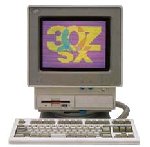
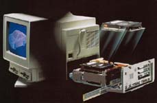
Photo image is took from a brochure dated 11-90.
So it should be Stage II. Video cable is longer than
Stage I system.
PS/55Z 5530ZS is the first model of MCA 5530 series (Except 5530Z-286 which
had been sold to closed market for marketing purpose). In order to reduce
retail price of expensive MCA line-ups, IBM Japan picked up i386SX CPU for
PS/55Z. The basic design might be derived from PS/2 Model 25Z as you can see
above photo. 12" color display was built in a body. Unlike PS/2 25Z, logic unit
is slide-in type (no need to set the system up-side down while accessing system
board and inner parts). AND, PS/55Z 5530 is an MCA system.
5530Z-SX is deviled to two groups, S0x and S1x
(Ed: The former is refereed as Stage I and the
latter as Stage II). All models use 386SX-16MHz.
The 5530, 5530-T04/T08 (Stage II) and 5530-S12/S14 (ZSX on Stage II)
were listed in the Nov 1990 edition of the PS/55 System Guide.
Specification of Stage I Type S0x
| Type |
HDD |
OS |
| S02 |
None |
not included |
| S03 |
30MB |
not included |
| SJ3 |
30MB |
JDOS4.0 preloaded |
| S06 |
60MB |
not included |
| SJ6 |
60MB |
JDOS4.0 preloaded |
Memory: 2MB standard (MAX on a planar; 4MB)
FDD: 2 Mode drive (1.44MB/720KB)
Options:
56F9045 : 80387SX/16MHz Math co-pro
38F7075 : 512KB VRAM Upgrade
56F9046 : 2MB System memory kit IV
23F3084 : 1MB System memory kit
57F0112 : 3.5" internal FDD III (2 mode + 1.2MB/Read only)
56F9007 : 60MB Hard drive (ESDI)
56F9006 : 30MB Hard drive (ESDI)
38F4816 : Cable, Video Signal Extension.
Specification of Stage -II Type S1x
| Type |
HDD |
OS |
| S12 *1 |
None |
not included |
| S14 |
40MB |
not included |
| SJ4 |
40MB |
JDOS4.0 |
| Windows model released in Mar. 1991 |
| SW4 |
40MB |
DOS4.0/V & Win3.0 |
*1: S12 was equipped with 2 FDDs.
Memory: 2MB standard (MAX on a planar; 6MB)
FDD: 3 Mode drive (1.44MB/1.2MB.720KB)
Options:
56F9045 : 80387SX/16MHz Math co-pro
64F9668 : 512KB VRAM Upgrade
79F2536 : 4MB System Memory kit VI
79F2556 : 2MB System memory kit V
23F3084 : 1MB System memory kit
79F1796 : 3.5" internal FDD VII (3 mode)
79F1795 : 40MB Hard drive (ESDI)
74F1781 : 3.5" Optical Drive (Requires SCSI /A)
6450609 : 2-8MB 80286 Mem Expansion
(SIMM; 6450604/2MB, 6450603/1MB)
Different VRAM option P/N for Display Adapter were listed in system
guide. I'm not sure if there are two variations for Display Adapter
/IV.
System Unit (from 30ZSX Stage-I Quick Reference)
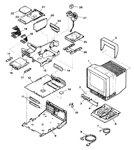
1 Display and Front Cover Assy
2 Label, Serial Number
3 Bezel. Diskette Drive
4 Bezel, Blank
5 Flap Assembly
6 Pedestal Assembly
7 Cable, Signal Ground
8 Power Cord (2P)
9 Cover, Base
10 Security Key Assy
11 I/O Blaket- Blank
12 System Board
13 i80387SX, 16MHz Module (Op)
14 2MB Memory Card
|
15 Option Adapter Guide Block
16 1.44MB diskette Drive
17 Guide, Diskette Drive (L & R)
18 Cable, Flat, for one FDD
19 Cable, Flat, for two FDD
20 Interposer Card (Option Slot)
21 Display Adapter IV Card
22 Display Expansion Card (Op)
23 Spacer (Op)
24 HDD interface card
25 Fixed Disk Drive (ESDI)
26 Guide, Fixed disk drive
27 Speaker Holder Assy
28 Battery
|
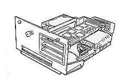
Accessing System Board (From users manual 2nd edition dated Nov 1989)
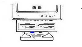 |
Slide the blue lock lever to the left and lock the system unit not to swing.
|
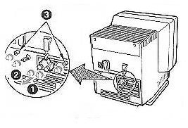 |
Detach video connector from PS/55 Display adapter placed at the most upper
slot (Display adapter IV should be placed there).
Unscrew two knobs at the middle of rear panel.
|
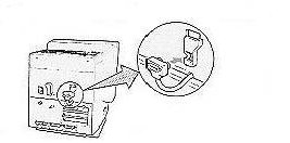 |
Place the connector to the "foxhole" prepared at the support guide for
the connector cover.
Note: The video cable is very short and will not
reach to the middle slot.
|
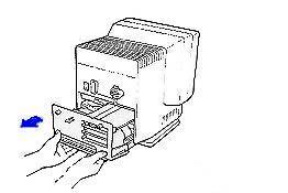 |
Grab the bottom edge of the base unit and pull it backward
slowly till it will stop sliding.
|
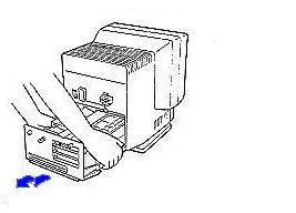 |
Hold the base unit and pull it upward slightly and then slide it backward
so that you can pull the base unit completely.
|
 |
Done!
|
5530-S Planar P/N 56F7420
![Front [P]](/other/img/photo.gif)
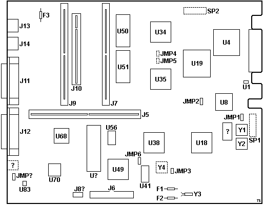
F1 3A fuse
F2 2A fuse
F3 2A KB/mouse fuse
J5? Bus riser slot
J6? 34-pin floppy connector
J7 72-pin SIMM slot #1
J8? Battery connector
J9 72-pin SIMM slot #2
J10 Hard driver riser slot
J11 Parallel port
J12 DB25 serial port
J13 Mouse port
J14 Keyboard port
JMP1?,2,6,? 3-pin jumper
JMP3 2-pin jumper
JMP4,5 Pads for 2-pin jumper
SP1,2 "spare" DIP-20
U1 M51943BML reset circuit
U4 90X8134 DMA ctrl.
U8 i386SX-?
|
U18 27F4619
U19 i387SX co-pro socket
U34 27F4620
U35 57F1139
U38? 37F0728?
U41 ?
U49 23F8566?
U50 ROM Even 64F8908
U51 ROM Odd 64F8909
U56? ?
U? NEC D765BC
U68? ?
U70 23F3001?
U86 LM386 Audio op-amp (PC Speaker)
Y1 32.000 MHz osc
Y2 14.318 MHz osc
Y3 32.768 kHz xtal
Y4 Pads for 1.843? MHz osc
? Delay line?
? Pads for 3-pin connector?
|
5530-S Bus Riser Card P/N 56F7429D
![Front [P]](/other/img/photo.gif)
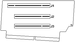
J1 16-bit MCA slot w/ AVE
J2,3 16-bit MCA slot
5530-S HDD Interposer Card P/N 57F0143
![Front [P]](/other/img/photo.gif)
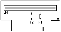
F1,2 5 and 12 V rail fuse?
J1 DBA hard drive connector
Blog Post about PS/55 Z on modelrail.otenko" (with many photos)
PS/55 Model 5530-T
Model 5530-T Brochure
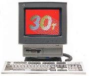
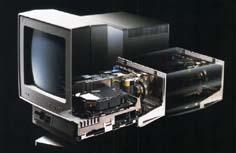
The body, outer case and screen are all same with model 5530ZSX.
i386DX-20MHz CPU was given and the model was classified to PS/55.
(Want to see sales brochure? Click HERE)
A sales brochure of 1st model of 5530-T (T03 & T06) was dated as 11-89
which means Nov. 1989.
If so, 5530-T03/06 was Introduced to the market together with 5530Z-SX in Nov.
1989.
Next models, T02/T04/T08, were introduced in OCt. 1990.
CPU
386DX-20MHz.
486BL2-66 upgrade sub-board from Kingston was available.
To use this parts, an interposer which changes the position of
pin #1 is required. Not sure for 486BL3 upgrade by Evergreen if it
could be fit in the planar.
Built-in Display
12" color display (long persistence phosphors) was integrated
into the body.
Character mode ; 1066 x725 dots
Graphics mode; 1024 x768 dots
SIMM
72pin SIMM socket x 3. 2MB/80 ns parts is standard.
One double-decked 4MB SIMM P/N 23F2165 can be used.
Total 8MB in combination of 2MB+2MB+4MB is the MAX on the planar
according to users guide.
Actually 5530-T can take 24MB of RAM in combination of 3x 8MB 80 ns SIMMs
on the planar. Not sure if PC DOS 7 can actually see total 24MB of RAM.
I've tested JDOS5.0 + HIMEM.SYS in PC DOS 7.0 on the box but I got
only 16MB of RAM reported using MEM command (this combination works for
other 486 class PS/55s).
23F3270 2MB ; memory kit III
56F9046 2MB ; memory kit IV
79F2566 2MB ; memory kit V
79F2536 4MB ; memory kit VI
79F2467 8MB ; Could be usable too.
2-8MB memory expansion 23F3056
HDD
ESDI (DBA2) 30MB to 80MB depending on model-type.
T02 was 2 FDD model and without HDD.
FDD
2 Mode drive for all models.
BUS Riser
5530-T has only 3 MCA slots on it's riser card. 1 slot should be occupied with
a PS/55 Display Adapter, hence only 2 slots are left for users.
Reference
Version 1.50 based on DOS/V is the latest.
In order to use XGA, XGA-2 and SVGA /A you need to use Ver.1. 50.
The original Reference is based on JDOS and with the original version,
option disks for SVGA or XGA can't be read.
The Ref version 1.50 can be commonly used for model 5550-S/T/V, 5570-T/V,
5540-T, 5545-T.
Video
PS/55 Display Adapter IV (512KB VRAM; Optional 512KB VRAM board was
available) was used for 5530-T and 5530Z-SX.
Video cable from display unit is very short in its length and it will
not reach except the most upper MCA slot where a stock AVE Video
Adapter IV should be placed.
IF you are planing to use XGA or any other Cirrus based Video Adapter,
you have to use one of lower two slots to which the video cable will not
reach. Thus you have to use appropriate video extension cable with D-sub
15pin female on one end and D-SUB 15 pin male on the other end.
38F4816: Cable for Video signal Extension is listed in Service
Summary for 5530-Z.
5530-T Planar P/N 78F9969
![Front [P]](/other/img/photo.gif)
Three 72-pin SIMM sockets, HDD riser, MCA riser.
Outline not available yet.
2nd Generation of 30 line; 5530-U/V Models "Florence"
Model 5530-U Brochure
Model 5530-V Brochure
RICOH PS 5530-W/V Brochure
Newly designed 30 series was started with PS/55Z 5530-U. Built-in display
was changed from 12" to flat type 13", planar and the BUS riser were also
rearranged. 30-T/S provided only 3 MCA slots but newly designed body and
planar/riser provided 4 MCA slots though dimension was almost same with the
older body. 3 mode FDD (1.44MB/1.2MB/720KB read/write capable) was used for all
models. Video cable from display unit is longer than older models so that the
cable reaches to the second slot.
PS/55Z
5530-U
(U01/UV1/UW4/UW8) |
386SX20 |
FDD x1, ESDI HDD, XGA /A.
Windows3.0 was pre-loaded together with DOS J5.0/V for UW4/8 |
| 5530-UAx |
IBM 386SLC20 |
This model was called 30U-SLC. |
5530-V
(V04/V08/VJ8/VY8) |
IBM 386SLC20 |
Basically same with 30U-SLC but 30V was equipped with Japanese Display
Adapter instead of XGA /A.
OS/2 J2.0 was pre-loaded on VJ8 & VY8. |
5530-V28/VA8
5530-VX8/VXB |
IBM486SLC2-40 |
V28 & VA8 were equipped with a PS/55 Display Adapter/A.
VX8 & VXB were equipped with an XGA-2 /A.
OS/2 J2.0 was pre-loaded on VA8 & VXB.
5530-V2 was the last 386 class model. |
New 386 Planar
U and V planar are almost same. 386SX20 on a U planar was changed to
IBM386SLC20 and J1 beside the power connector is shifted beside U1 like V2
planar below.
V2 planar has aux power outlet J22. J10 on U/V planar is not seen on V2
planar. Y3 (CPU clock OSC) is shifted backward.
5530-U/-V Planar P/N 79F5393 (-U?)
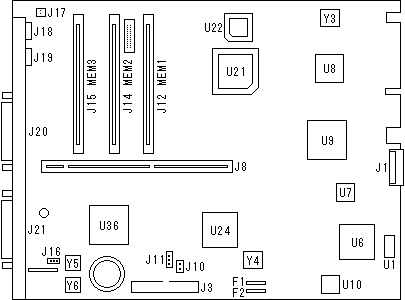
J8 Bus riser slot
U6 95F4436
U7 20R6
U8 i386SX-20 CPU
U9 92F1495 System controller?
U10 Dallas DS1285Q RTC/CMOS
U21 387SX co-pro socket
|
U24 82077AA Floppy controller
U36 91F7490 I/O controller?
Y3 40.00 MHz
Y4 24.00 MHz
Y5 14.3185 MHz
Y6 22.1184 MHz
|
5530-V2 Planar P/N 54G0084
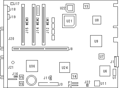
J8 Bus riser slot
U6 95F4436
U7 20R6
U8 IBM486SLC2-40 CPU
U9 92F1495 System controller?
U10 Dallas DS1285Q RTC/CMOS
U21 387SX co-pro socket
|
U24 82077SL Floppy controller
U36 91F7490 I/O controller?
Y3 40.00 MHz
Y4 24.00 MHz
Y5 14.3185 MHz
Y6 22.1184 MHz
|
Bus Riser Card for 5530-V2?, "RISER CARD 16", "IGH0615AA"
P/N 79F4918, EC C80787, FRU P/N 95F4218
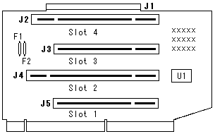
There is another 16-bit riser with different P/N which has silk printings
as follows (perhaps for 5530-U/V):
INTERPSER
P/N 95F4218
EC C80670A
Basically these risers are same except P/N 95F4218 has 2 registers and 2
capacitors and 2 rework wires on the solder side of the PCB.
Options
| Item |
ID# |
Price
May 92 |
Price
Apr 93 |
| Minny Mouse |
07G0532
|
12,000 |
|
| 80387SX-20 co-pro |
07G0553
|
120,000 |
60,000 |
| 2MB Memory kit |
79F5395
|
50,000 |
30,000 |
| 4MB Memory kit |
79F5396
|
100,000 |
56,000 |
| 8MB Memory kit |
79F5397
|
200,000 |
104,000 |
| 3.5" Diskette Drive |
95F4388
|
40,000 |
|
| 3.5" Diskette Drive (4Mode Drive) |
54G1680
|
|
34,000 |
| 80MB Hard Drive (ESDI) |
07G0536
|
200,000 |
|
| 160MB Hard Drive (ESDI) |
07G0554
|
300,000 |
|
| 100MB SCSI Hard Drive *1 |
35G2839
|
200,000 |
140,000 |
| 200MB SCSI Hard Drive *1 |
35G2840
|
300,000 |
240,000 |
| 3.5" Optical Drive (MO) |
79F1781
|
298,000 |
298,000 |
| SCSI Adapter /A (16-bit) |
64F9050
|
61,000 |
|
| SCSI Adapter -II/A (32-bit) |
06G6760
|
88,000 |
88,000 |
| TokenRing Adapter |
4773083
|
130,000 |
|
| TokenRing 16/4 Adapter |
93F2970
|
142,000 |
142,000 |
| Ethernet Adapter 10Base 2/5 |
35G2793
|
87,000 |
|
| Ethernet Adapter 10Base T/5 |
35G2806
|
58,000 |
|
| MultiProtocall Adapter IV /A |
95F4528
|
58,000 |
|
| Modem Adapter /A 300/1200/2400bps |
79F2658
|
49,800 |
|
Hard to believe there were ordinal users who could buy such expensive
peripherals for personal usage.
5530-W/W2
RICOH PS 5530-W/V Brochure
Real 486 planar which was developed for desktop model 5550-W was used for
5530-W.
CPU:
5530-W0x: i486SX-20
5530-W2x: i486DX2-40
Note that 5530-W is IML system.
Options:
i487SX co-processor : 07G3013 , Price 200,000
486-20/40 Processor Upgrade Option : 35G2996 , Price 280,000
5530-L
The last Emperor of the True MCA "all-in-one" Model 30 line
Model 5530-L Brochure
5530-L Product Page (archived, JP)
5530-L Product Page (local translated copy)
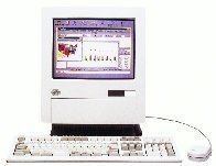
5530-LXC |
5530-L was the last model of PS/55 30 series. It's really a
nice machine with a 486 class L planar and integrated 13" color display. IBM
486-BL2/66 was soldered on the planar and a ZIF socket for an overdrive
processor was ready on the planar. Unfortunately the socket is not PODP ready,
it's a Socket 1.
If you have a R planar for desktop 5551-R which has ZIF socket 3, you can
make your own "5530-R" which was not released by IBM Japan.
|
| Planar | Same with 5551-L except for power connector |
| CPU | IBM 486BL2-66 with Overdrive socket (ZIF socket 1)
Accept ODPRDX4-100. DX4-100. Also accept AMD 5x86 and Cyrix with voltage interposer.
PODP can't be used for this model. |
| SIMM | 70 ns True parity SIMM x 4 slots |
| HDD | IDE |
| FDD | 3-Mode drive (1.44MB/1.2MB/720KB) |
| MCA Slots | 32-bit x4 (Full size x 3, half size x 1) |
| Video | Type LXC : XGA-2
Type L0C : PS/55 Display Adapter /A (Possibly DBCS D/A /NI-J) |
| Reference | Ref. ver. 1.21 (Same reference with 5551-R/L and 5521-Y) |
| Diag | Diag. ver. 1.21 (Ditto) |
32-bit Riser Card "RISER CARD 32", "IGH0866AA"
P/N 66G8882, EC D43566
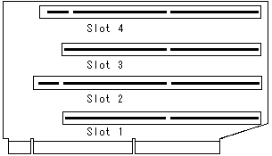
Dimensions of the riser card are same with 16-bit card.
Slot #2 is BVEC and XGA-2 or DBCS D/A /NI-J should be installed on this slot.
I suppose 5530-W uses same riser card.
Pictures of my 5530-L
(w/ the 5530-R planar installed in it)
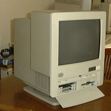 |
Front view
4 slot PCMCIA /A can be
seen in the left bay where the FDD sits in a stock configuration.
To install 4 Slot PCMCIA Adapter, FDD should be moved to the right bay. This
adapter can be used solely in this newer 30 body. Unfortunately I don't have a
front bezel to mate with this adapter.
|
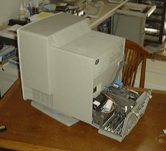 |
Rear view
Base unit is half-pulled out. |
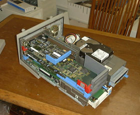 |
Base unit
From the bottom, you can see:
1) 4 slot PCMCIA/A,
2) XGA-2,
3) Madge Smart RingNode 16/4,
4) Short PS/2 Adapter/A for Ethernet networks with SMC chip.
DSAA 720 is loaded at the HD sled.
Thus this machine should be named as 5530-RX7: R planar with XGA-2
and 720MB HD.
|
|