|
Operator/Indicator Panel
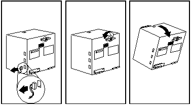
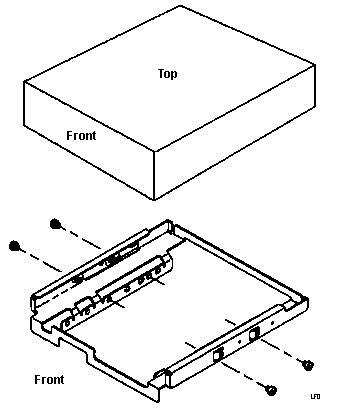
Opening and Closing the Case
Ventilation Requirements
Installing Memory
Mounting Hardware for Disk Drives
Install Floppy Drive
Remove Rail Guide from Storage Trail
Inserting Rail Guides
5.25" Drive Rail Dimensions
3.5" Hard Drive Mounting Tray
Tubular Lock Manufacturer
Installing Memory
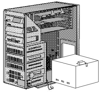
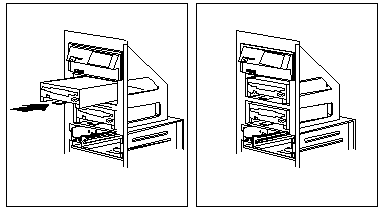
1. Tilt out the power supply:
Caution!
When you tilt out power supply, do not let it drop.
Personal injury or damage to the server might result.
Note: Be sure the AC power
cord is removed from the server before you try to tilt out
the power supply.)
a. Disconnect the drive power cables from the power supply.
b. Unscrew the blue spring-loaded retaining knob until it releases.
c. Place one hand on top of the server to support it.
d. Tilt out the power supply with the other hand.
2. Locate the SIMM connectors. SIMMs must be matched pairs (size,
speed, and type) in most cases (see machine-specific info).
Note: You can use mixed
speeds in the same pair, but the memory will be accessed
at the slowest speed. All memory must be the same type
(parity or ECC). Install SIMMs in the
following order: A1-B1, A2-B2, A3-B3, A4-B4.
Layout of SIMM slots and banks:
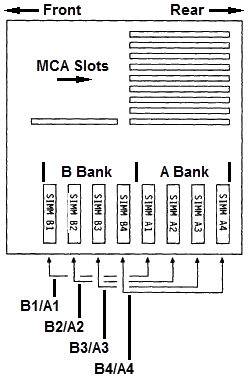
Example: Matched SIMM pair installed in slots A1 & B1:
3. Touch any unpainted metal surface on the server. This equalizes the
voltage potential between you and the system. Then remove the SIMM from
anti-static package (if applicable) and do a visual inspection to make sure
the module isn't physically damaged.
4. Install the SIMM modules:
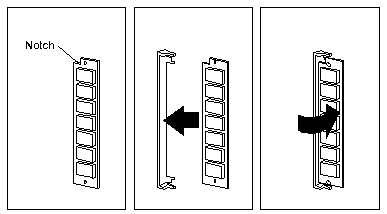
a. Turn the SIMM so the notched end faces
the top of the server.
b. Insert the SIMM into the connector.
c. Pivot it to the right until it snaps into place.
d. Repeat these steps for each SIMM you install.
SIMM Orientation
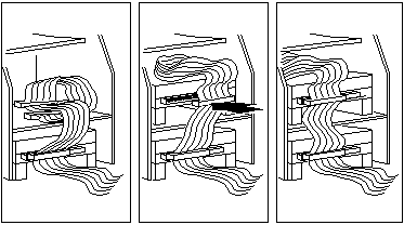
5. Reinstall the power supply:
a. Move all the internal power and SCSI cables
out of the way.
Note: If you
have a SCSI CD-ROM with an external terminator on it in
the single 5.25" bay, this is referred to as a
"guillotine"! Push the CD-ROM drive forward, then hold
the SCSI cable towards the front of the case while
rotating the power supply back in. Or you WILL be
sorry...
b. Tilt the power supply into the server.
c. Press in the retaining knob and turn it to the right until it's tight.
Note: Do NOT tighten the blue knob more
than finger tight! Otherwise the e-clip will be deformed and it will fall off...
More details HERE.
d. Reconnect the drive power cables to the power supply.
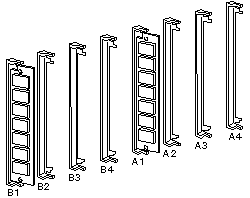
Mounting Hardware for Disk Drives
Drives come in a variety of heights. You can
install half-high drives that are less than 41.3 mm (1.6
in.) high in any of the bays. Drives that are
greater than 41.3 mm (1.6 in.) high (full-high) can be
installed in bay C or bay D. Bays C and D can each hold
two half-high drives or one full-high drive.
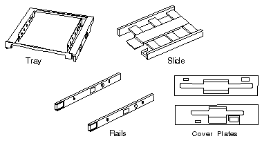
Slide
- Mount floppy drive sized devices in Bays A and B
(floppy, tape, or PCMCIA)
Tray -
Mount 3.5" drives in the 5.25" drive bays.
Note: You will need Rail
Guides in the DASD Support Structure!
Rails
- Mount 5.25" drives (floppy, CD, HD)
Cover plates (sometimes called bezels) cover
the front of each installed drive. If you install a drive that
uses removable media (diskette, tape, optical disc, or
CD), you will need to change the cover plate.
Tape Drive Bezel 34F2721 34F2719
Installing Floppy Drives
Install the diskette drive in bay A or B:
Note: The figures that accompany these steps show
the installation occurring in bay A. These
instructions also apply to bay B.
a. If a flat cable is folded inside bay A,
unfold it and route it along the back of the bays.
b. Position the drive so the connector is
facing the rear of the server.
c. Align the drive with the guides on the
bottom of the bay.
d. Slide the drive into the bay until it
stops.
3. Locate the connector on the flat cable directly
behind the bay you are using (A or B), and connect it to
the back of the drive.
Note: For bay
A, use the middle connector (labeled "P2-1"). For bay B,
use the bottom connector (labeled "P2-0"). FWIW,
P2-2 is for a floppy tape backup OR for a 5.25" floppy.
| FRU | Description |
|---|
| 64F0156 | 3.5" Floppy Drive Slide |
| 64F4102 | 1.2MB 5.25" Floppy |
| 85F0040 | 5.25" Floppy Drive Slide |
| 85F0041 | 5.25" Floppy Rail Kit (Use 5.25" Drive Rail) |
| 64F4103 | 5.25" Floppy Bezel |
Remove Rail Guide From Storage Tray
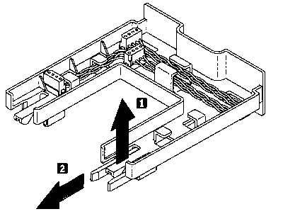
Pull up on the tab (1) on the back of the tray and pull
out the rail guides stored on the bottom of the
tray.
| FRU | Description |
|---|
| 84F8075 | Storage Tray |
| 60G9827 | Rail Guide |
Inserting Rail Guides
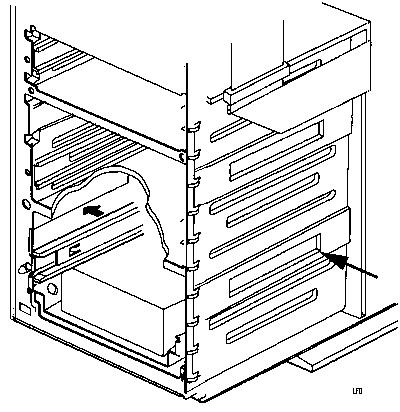
Press a rail guide into each side of the DASD support
structure. The left and right guide rails are the same.
5.25" Drive Rail Dimensions
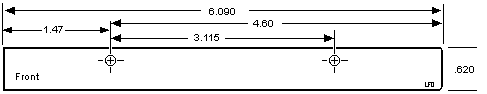
I measured this from a single RAID bay.
HD Mounting Tray
85 P/N 85F0013
95 P/N 64F0141
Ed: My 9595s are stamped 10G4769.
Note: The drive may
be installed in the tray with the mounting screw flange
pointed down (as pictured) or pointed up. This is
helpful if you have a mix of 1.6" and 1" drives to
install.
The 3510, 56, 57, 76, 77, 85, and 95 all use the same
HD Mounting Tray.
Hard Drives can be mounted with the mounting screw
frame on the lower side, or the mounting screw frame
above the rails.
Tubular Lock Manufacturer (from Al Brandt)
The manufacturer of the lock cylinders for the Model 85/95 is:
Rexnord Camloc
601 Route 46 West
Hasbrouck Heights, NJ 07604
USA
|