|
Table of Contents
[-0-] Version History, Disclaimer & Legal Info
[-1-] Precautions and Warnings before you start
[-2-] Introduction to the Type 4 "Y" Pentium 90 Platform
[-3-] The importance of cooling certain components
[-4-] Modification A) Using a Pentium Overdrive 180 / 200
[-5-] Modification B) Hardwiring the BF0 / BF1 Pins for different Bus / Core ratios
[-6-] Modification C) Changing the Base Clock from 60 to 66 MHz
[-7-] Modification D) Using a Pentium MMX 233 MHz with an Interposer
[-8-] Problems, Workarounds and other stuff
Content by Peter H. Wendt (original HERE). Edited by Major Tom.
The importance of cooling certain components
It is a well known phenomena that flow of electricity
through a load produces heat. This effect, that is desired if we are talking
about electric heatings, may become a problem in the "silicon world".
If you carefully touch surface of the processor complex chips, you will find
that some of them get pretty hot during operation.
Some components - namely the voltage regulators and the processor itself -
have heatsinks installed to help with heat dissipation to the surrounding air.
Other components don't have this luxury, but that doesn't mean they
don't get hot during operation.
Note: Component temperatures will be
significantly higher if you run the machine with the side/top cover removed,
because doing so disrupts the intended airflow! This is especially true
for the Model 95, where not only the air path is affected, but without
the panel installed, you are also missing the
squirrel cage fan that normally
sits right above the processor complex! If you intend to run the system in this
configuration for a prolonged periods of time, consider using an external fan
to force some airflow over the processor complex (and adapter cards) to
avoid overheating.
As a "rule of thumb" (not only figuratively) you can do the following
test: wet your finger a bit and touch the surface of one of the components
(Ed. be careful not to touch any exposed component leads, you may short and
damage something!). If the water evaporates immediately it's
above 75 °C - and most likely too hot to touch with a bare
finger anyway. Any temperature below 60 °C is not just "nice to touch" but
you should be able to withstand it for several seconds. If you are able to keep
your finger on that particular part for a very long time, it will surely be
below 50 °C.
Not a qualified testing method, and YMMV, but it's a decent quick-test to
find any hot running components...
Many semiconductors are designed to operate reliable at temperatures above
100 °C - at the chip core, which may result in about
75 - 85 °C surface temperature - depending on the package type
and some other aspects. But the general rule here is - cooler it runs,
longer it lives (unless you decide to use LN2 for cooling... you
may be able to break some overclocking records that way, but you will likely
break your hardware as well sooner or later).
Every "chip tuner" should be aware of the fact that the attempt to
speed up the board functions will cause more heat. So it's not ok
to rise the clock frequency, alter the pinout a bit, and just hope
that the technical reserves of the original design will allow for a
reliable operation.
If you speed up the external clock, and if you switch to a
higher performance processor, it will have an impact on the heat
generation. The very least you can expect is an increased power consumption
- by the processor in the first place, along with higher power drawn by
the accompanying chips as well - which results in a higher load on the
3.3 V voltage regulator. Which then results in an increased heat production of
that part - as well as higher heat production of the processor itself.
So, there you have the first two places where you need to do something -
where you have to improve the cooling.
A good reference on how to modify the heatsink for the LT1084 3.3 V
regulator can be found on Jim's
P90 Complex Technical Considerations page.
Jim has done a major research on this topic, and offers some very good
and easy to do modifications. All say, Thanks Jim!
For the processor there are many different cooling kits available. Most
cooling solutions designed for the Socket 5, Socket 7 and Super 7 platforms
should be compatible without any modifications (as long as they are not too
bulky...). The newer Socket 370 is similar in its physical construction, and most
heatsinks designed for this platform are somewhat larger (which may be a good
thing, unless they are too monstrous) and should be also usable with Socket 5/7
based boards and CPUs ...with some minor modifications that is. More
specifically, the retaining clip may be too long and may not align correctly
with the socket base (and that's where the mounting hooks are). So, you may
need to get a bit creative if you want to use one of these newer sportier
coolers. The P90 platform comes with an older and somewhat different retention
mechanism than most later systems - a simple wire spring. However the CPU socket
itself has a provision for both mounting methods - the spring, and the clip
(well, or at least it should have both, unless IBM used a different socket on
some boards, and unless somebody managed to break it off, you better check
first).
The clip is not there just to prevent the heatsink from falling off, it
also applies a small amount of pressure, to ensure proper contact between
the two surfaces (CPU package and the heatsink). But make sure the pressure
isn't too high, otherwise it may break off one of the flimsy plastic hooks
on the processor socket. The target pressure is nowhere near to what later
CPUs like the Pentium 4, AMD Athlon XP and later require, so don't over do it,
or you will break things! You should be able to install the clip with just
two fingers and without applying too much force
Before you install the heatsink don't forget to clean both surfaces (with
alcohol if possible), and apply a fresh thermal interface material (TIM) -
thermal paste or thermal pad. It will compensate for all the minor imperfections
of the two mating surfaces, and will significantly improves heat transfer
capabilities. If you are using a paste, put a pea-sized amount of it to the
middle of the CPU surface and then install the heatsink. You don't have to do
anything else, it will spread and even out on its own, once you apply a
pressure on it via the retention clip No need to use any special or magical
"patterns" when applying the paste - it would spread from a multiple places and
you risk trapping some of the air inside that way, which is not ideal.
Simpler is better here. But hey, we are talking about CPUs with TDP < 20 W,
so it doesn't matter that much really...

|
Older processors like the P90 - 150 mostly used an all-ceramic package
(CPGA) with a relatively large and flat surface area. In terms of heat
distribution this package is sub-optimal, because the ceramic material is
rather thick, and keeps the heat inside longer (low heat transient /
dissipation factor).
|

|
Later versions had a ceramic package with a metal (typically gold-plated)
cap - the so-called "integrated heat spreader" or IHS. The heat spreader
doesn't cover the entire surface area and is not of the same height as the rest
of the package, which limits the contact area significantly.
|
|
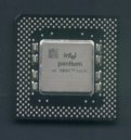
Most Pentium MMX processors came in a plastic package (PPGA) with even
smaller and somewhat taller IHS (it has to be taller to clear the on-board
bypass caps). Some of the later Classic Pentium processors (Non-MMX) also
inherited this package - like for example the P166 and P200 parts.
|
There are some other components on the P90 platform that get somewhat hot
and are worth keeping an eye on as well. The 82497 cache controller is
one of them. You can use Socket 5/7 cooling solutions for it, but you will
have to modify the mounting mechanism most likely. A Socket 5/7 cooling kits
that use a clip over the heatsink cannot be used. The 82497 socket lacks
the clip catches typical for Socket 5/7.
The 82492 cache SRAM chips get fairly hot as well. There is 10 of them
total. Fortunately there are 5 of them on each side of the board - located
opposite each other, so you could try to get 10 smaller heatsinks (like
the one used on earlier revisions of the XGA-2 card RAMDAC) and make 5 c-shaped
metal clips - one for each SRAM pair. Since you need to use thermal
conductive paste that is by nature rather sticky, you will surely manage
to affix the two adjacent heatsinks and bring your self-made clip over this
lovely sandwich (between the heatsink fins). Once again the clip should apply
some pressure onto the two heatsinks to press them onto the SRAM chips to
ensure proper thermal contact.
Alternatively you can get a ready-to-use heatsinks with a pre-applied thermal
conductive adhesive, and simply stick them to the SRAM chips one by one (or
get one long low-profile heatsink for each side, but first check that all
SRAM chips are at the same level... if not, you would have to use thermal pads,
to compensate for the difference). This probably won't provide heat transfer
as good as the first method, but it should be good enough for this application.
Use heatsinks with a high-quality adhesive if you decide to go down this road,
you don't want them to fall off and rattle inside the machine... posing a
short-circuit risk.
(Unfortunately I haven't managed to get appropriate heatsinks in the required
quantity so far. The heatsinks used on old 4 Mbit Token Ring adapters could
potentially be used - but they have some sort of side guides that would have
to be milled down, otherwise they could short some of the SRAM pins.)
Now, I am known as a person that a) does many things
"my way" and b) likes to recycle items that just lay around collecting dust.
So, I've found another - perhaps silly - but simple - solution. Look here:
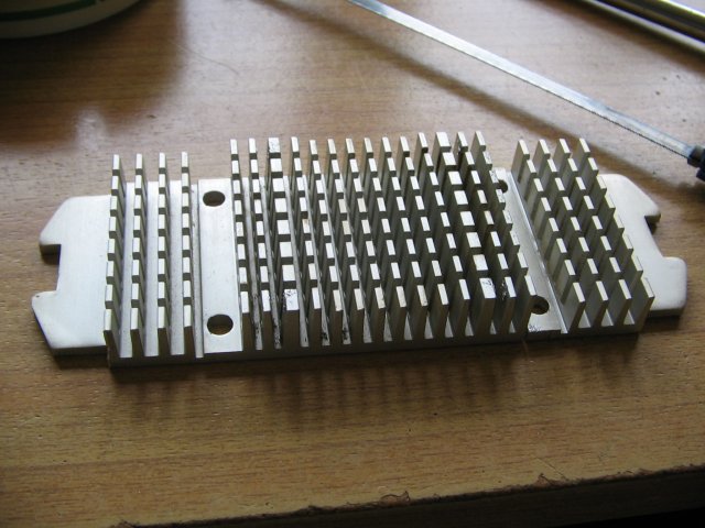
A generic vertical fin Slot 1 heatsink |
Trimmed a bit, fits nicely |
| |
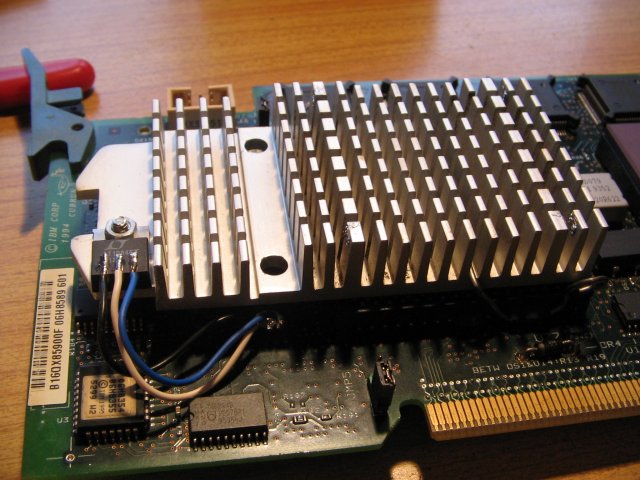
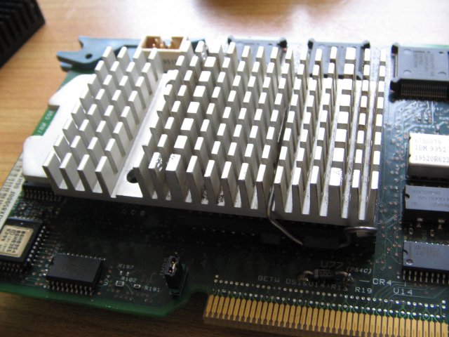
LT1084 regulator installed... |
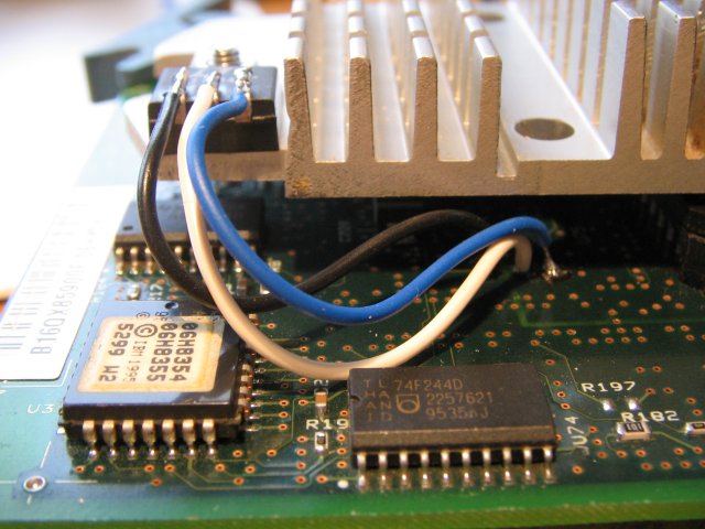
...and wired to the PCB |
One day I came across this Slot 1 heatsink. It was still attached to an
Intel Celeron 266 MHz CPU, which was of little interest to me. But the
heatsink height nicely matches Socket 5 CPUs. A charming and not unimportant
detail is the fact that the heatsink fins run top down - as required by the
airflow from the side panel fan.
Hooray! It even had a silicon rubber pad on the underside...
and it was about the same size as the Pentium chip. I've decided to trim
off one side of the heatsink - along the first fin row, and keep the other
side as a post to mount the voltage regulator.
As you can see: It looks relatively good.
I've used a complex that has been considered dead. It wouldn't POST or
display anything on the Op Panel, so I've guessed it must be a DC supply
problem. But as a testbed it came handy. So I soldered three wires
to the original regulator position and hooked them to a LT1084 regulator.
I've bent the legs up and trimmed them a bit. (Don't bend
the legs too close to the package itself - they will break off! Use a thin
screwdriver and bend the legs around it. Or don't bend them at all.
Make sure not to solder the wires too close to the package. The heat could
damage the chip inside. Leave them at least 5 mm long.)
Next I drilled a 2.5 mm hole into the heatsink, cut a thread into it, drilled
the underside with a larger - 6 mm drill, 3 mm deep, and put a M3 lens head
screw into it. That helps to keep the underside relatively flat. Not
that it matters much - there's plenty of space. But I have the nut at the upper
side. I've used a silicon insulator sheet and a plastic washer under the
nut in case the heatsink gets grounded somehow. The metal tab of the regulator
is connected to the middle pin (2), which carries the output voltage (3.3 V
in this case).
Then I stuffed a P133 CPU into the socket, installed the heatsink/regulator
combo, secured it with the original metal spring, and installed the complex
to my testbed 95A.
Of course it didn't work...
Out of curiosity I've measured the voltage on the
regulator and it was only about 2 V. Hmm... After some more testing I've found
out that the pin 2 contact hole must have got damaged - probably during one of
the previous experiments with a switchmode regulator. I've used a little longer
wire and fed it through the PCB hole that used to hold the original small
heatsink, then towards the underside of the CPU, and there to the + marked ends
of C177 and C162. These two are the only caps on the 3.3 V rail.
C210 is 5 V... Watch out!
To my surprise the complex sprung back to life.
So far I've done only a few relatively short tests with this board.
Subjectively the heatsink doesn't get too warm to the touch, but I've only
used a P133 with the faster ticking 66 MHz oscillator. So it runs
at 133 MHz, even though the cache SRAMs and the cache controller are rated for
60 MHz operation only. I would take no bet that this LT1084 would not shutdown
under load and thermal stress after some runtime.
I would opt to replace the LT1084 (5 A) with the beefier LT1083 (7 A) part.
The LT1083 comes in a slightly larger package - but it would still fit, even on
the underside of the heatsink, at about the same place where the original
regulator and heatsink were located. It should even be possible to use one
of the already existing holes.
Am I mad or what? Comments please!
Results & Conclusions
After a few hours of stress-testing (with WinTune, etc.) the heatsink wasn't
warmer than maybe 45 or 50 degrees Celsius - which isn't too bad.
The regulator should really be moved to the underside. At its current location
it gets in contact with the SCSI cabling to the CD-ROM bay where I have a DVD
burner with IDE-to-SCSI adapter installed. The cable touches the heatsink
and it's next to impossible to reach it with a finger to check its temperature.
But it's probably doing fine temperature-wise. Don't know how much current it
has to put out, but it hasn't shut down so far. Not yet anyway...
Yet some more results
Recently I bought an Classic Pentium 200 MHz on eBay for just one Euro +
delivery costs.
I've removed the P133 from under the heatsink and while I was on it, I've
wired a multimeter in the 3.3 V line from the LT1084 regulator to monitor
the current draw. With no CPU installed it was less than 50 mA. Just the
pullup resistors and the leftover interface circuitry from the cache section
I'd guess.
That should leave enough leg-room for the "new" P200 CPU... Ok! I've
installed the processor, reinstalled the heatsink and put the complex back
into my testbed machine.
It came up as normal, but operated significantly faster. I've let it running
for a few hours, reformatted the HD and installed Windows 98SE on the machine.
After that I pulled the sidewall and checked the thermal conditions.
Well... the cache SRAMs and the cache controller appeared hotter than the CPU
heatsink.
I think the described modification is a good approach, as long as you
do not plan to use a Pentium Overdrive processor. For that you have to
stick with the original boxed fan, and you would have to find some other
solution to keep the LT1084 regulator happy.
|